Vibration system failures account for 35-42% of unplanned block machine downtime, costing manufacturers $1,200-$3,500 per incident in lost production and emergency repairs. A malfunctioning vibration system doesn’t just stop production—it produces weak blocks with 18-25% strength variations, surface defects, and dimensional inconsistencies that destroy your reputation in structural markets.
Manufacturers running automatic lines producing 12,000+ blocks daily lose $600-$950 per hour when vibration systems fail. The difference between smooth operations and chronic problems? Understanding how vibration systems actually work, recognizing early failure signs, and implementing targeted maintenance that prevents 70-80% of breakdowns.
How Block Machine Vibration Systems Actually Work
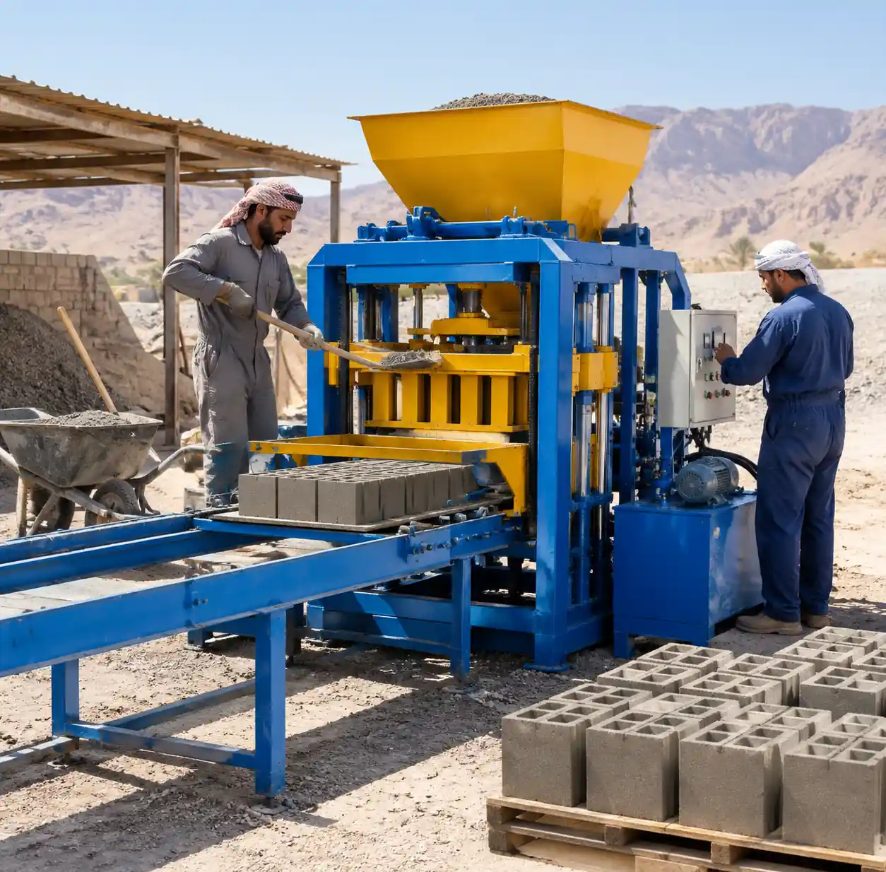
Block machine vibration systems use controlled oscillation to eliminate air voids and achieve proper concrete compaction. Unlike construction vibrators that operate randomly, block machine systems synchronize multiple vibration motors to create precise movement patterns that densify concrete uniformly across the entire mold cavity.
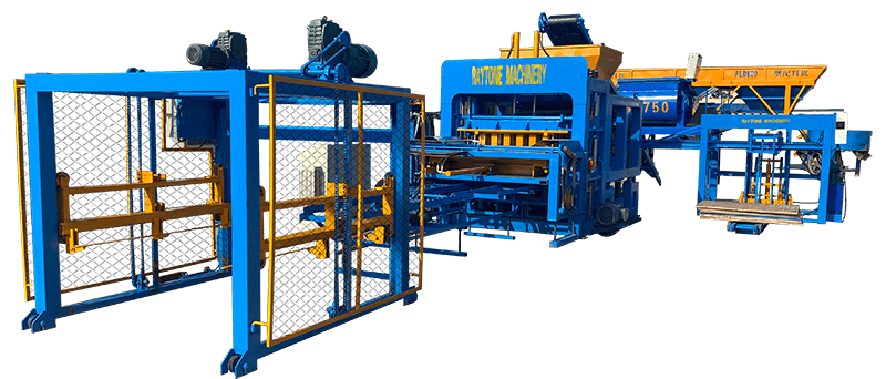
Most آلات الصب الأوتوماتيكية use dual-motor configurations: bottom-mounted motors (typically 7.5-11 kW each) provide primary compaction force, while top-mounted motors (3.7-5.5 kW) work against resistance to achieve thorough consolidation. Semi-automatic systems usually employ single-motor setups (5.5-7.5 kW) mounted beneath the mold table.
The vibration motor contains eccentric weights rotating at 2,800-3,600 RPM, generating centrifugal force that moves the mold table vertically. Adjustment bolts change the weight position, altering vibration amplitude from 0.3mm to 1.2mm. Frequency remains relatively constant at 46-60 Hz, determined by motor speed and pole configuration.
This synchronized vibration liquefies the concrete mixture temporarily, allowing particles to settle into optimal density. Properly configured systems achieve 2,200-2,400 kg/m³ concrete density in 8-15 seconds—the critical window before the mixture begins setting.
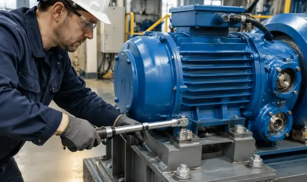
Critical Maintenance Schedule for Vibration Systems
| Component | Inspection Frequency | Maintenance Action | Failure Warning Signs | Replacement Interval |
|---|---|---|---|---|
| Motor Mounting Bolts | Daily | Visual check, torque weekly | Looseness, metal filings | N/A (retorque only) |
| Motor Bearings | Weekly | Listen for noise, check temperature | Grinding sound, >75°C temp | 4,000-6,000 hours |
| Eccentric Weight Bolts | Weekly | Torque verification | Vibration irregularity | N/A (replace if stripped) |
| Flexible Couplings | Monthly | Inspect for cracks/wear | Increased vibration noise | 8,000-12,000 hours |
| Motor Windings | Quarterly | Megohmmeter test (>10 MΩ) | Overheating, current increase | 15,000-25,000 hours |
| Vibration Isolators | Monthly | Check for compression/cracking | Excessive frame vibration | 12,000-18,000 hours |
| Cable Connections | Weekly | Tighten terminals, inspect insulation | Intermittent operation | Replace when damaged |
| Synchronization Timing | Monthly | Verify phase alignment | Uneven compaction | N/A (adjust only) |
Frequency and Amplitude Settings That Actually Work
Optimal vibration parameters depend on concrete mix design, block geometry, and ambient conditions. Most manufacturers ship machines with conservative factory settings that sacrifice production speed for reliability, but proper tuning can increase output 12-18% while improving quality.
Amplitude adjustment is your primary tuning variable. Hollow blocks 15-20cm high require 0.6-0.8mm amplitude. Solid blocks and interlocking designs need 0.8-1.0mm. Paver blocks and thin products work best at 0.4-0.6mm. Setting amplitude below 0.3mm prevents proper synchronization—motors run erratically and fail to compact uniformly.
Frequency optimization matters less because motor speed stays relatively constant, but variable frequency drives (VFDs) on advanced systems allow fine-tuning. Standard 50Hz power yields 2,940 RPM (49 Hz vibration), while 60Hz delivers 3,540 RPM (59 Hz). Reducing frequency 5-8% extends bearing life in harsh environments, though production capacity drops proportionally.
Vibration duration significantly impacts block quality and cycle time. Wet mixes (6-9% moisture) need 8-12 seconds. Dry mixes (4-6% moisture) require 12-18 seconds. Insufficient vibration leaves air voids; excessive vibration segregates aggregates and weakens blocks. Watch for concrete beginning to cream on the surface—that’s your cutoff point.
Cold weather below 10°C demands 15-20% longer vibration time as concrete stiffens. Hot conditions above 35°C allow 10-15% reduction but increase surface cracking risk. Adjust by observing demolded blocks—they should release cleanly without sticking or surface tearing.
Diagnosing Vibration System Problems
Weak or Inconsistent Compaction
Symptoms: Blocks show low crushing strength (below 3.5 N/mm² for standard hollow blocks), surface voids, or strength varies 15-25% between production runs.
Probable causes: Amplitude set too low (most common), motor bearing wear reducing effective vibration, loose mounting bolts damping vibration transfer, or failed vibration isolators transmitting force to the frame instead of the mold.
Diagnostic process: Place a smartphone with vibration analysis app on the mold table during vibration cycle. Properly functioning systems show consistent 48-60 Hz dominant frequency with 0.6-1.0mm displacement. Readings below 0.4mm or showing multiple frequency peaks indicate problems. Check motor mounting bolt torque—they should require 150-200 Nm depending on bolt size. Loose bolts feel obviously undertorqued.
Excessive Vibration or Noise
Symptoms: Abnormal grinding, squealing, or rumbling sounds. Frame vibrates excessively. Nearby equipment or structures resonate.
Probable causes: Bearing failure (creates grinding), motor imbalance from damaged eccentric weights, failed synchronization causing motors to work against each other, or deteriorated vibration isolators.
Diagnostic process: Isolate noise source by running motors individually if possible. Bearing problems produce metallic grinding that intensifies under load. Check bearing temperature—anything exceeding 80°C indicates imminent failure. Inspect eccentric weight bolts through motor covers. Missing or loose bolts cause severe imbalance. Failed isolators appear compressed, cracked, or separated from mounting plates.
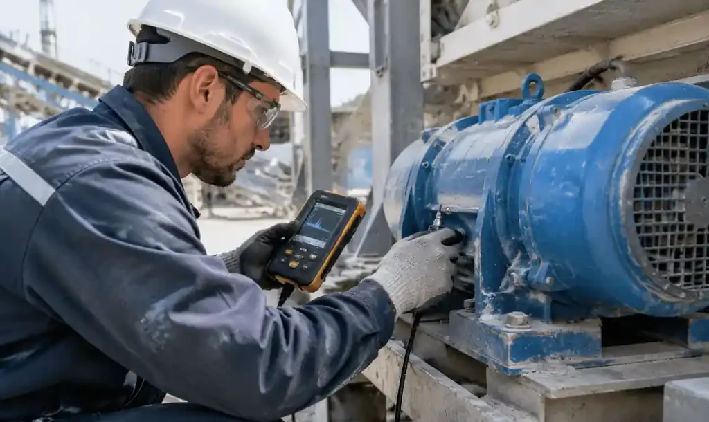
Motor Overheating
Symptoms: Motor housing temperature exceeds 80°C, thermal protection trips repeatedly, or insulation smells burnt.
Probable causes: Overloaded motor from excessive concrete batch weight, voltage imbalance exceeding 2%, restricted airflow from concrete dust accumulation, bearing friction from inadequate lubrication, or winding insulation breakdown.
Diagnostic process: Measure actual voltage on all three phases—imbalance over 2% causes 15-25% temperature increase. Clean motor exterior and ventilation ports thoroughly; dust buildup acts as insulation. Verify batch weight matches specifications—overloading by 10% increases motor current 20-30%. Check bearing condition by rotating motor shaft by hand when powered off; it should turn smoothly with slight resistance.
Synchronization Loss
Symptoms: Uneven block compaction, one side denser than the other, irregular vibration patterns, or visible phase differences between motors.
Probable causes: Mismatched motor speeds from worn bearings, voltage imbalance causing unequal power delivery, incorrect cable phasing, or different eccentric weight settings between motors.
Diagnostic process: Mark motor shafts with paint dots and observe during operation. Synchronized motors maintain consistent phase relationship; unsynchronized motors drift. Measure power consumption on each motor—differences exceeding 10% indicate problems. Verify cable phasing matches electrical diagrams. Check eccentric weight position on both motors—they must match exactly.
Performance Tuning for Different Block Types
| Block Type | Optimal Amplitude | Vibration Duration | Mix Moisture | Special Considerations |
|---|---|---|---|---|
| Standard Hollow 15cm | 0.6-0.8mm | 10-14 seconds | 6-8% | Most forgiving; use as baseline |
| Standard Hollow 20cm | 0.7-0.9mm | 12-16 seconds | 6-8% | Increase amplitude 15% vs 15cm |
| Solid Blocks | 0.8-1.0mm | 14-18 seconds | 5-7% | Drier mix, longer vibration |
| Interlocking Blocks | 0.7-0.9mm | 12-16 seconds | 6-8% | Clean molds critical for release |
| Paver Blocks | 0.4-0.6mm | 8-12 seconds | 7-9% | Lower amplitude prevents edge damage |
| Curbstone | 0.6-0.8mm | 10-14 seconds | 6-8% | Monitor for segregation |
| Lightweight Blocks | 0.5-0.7mm | 8-12 seconds | 8-10% | Reduce amplitude 20-25% |
Preventive Maintenance That Actually Prevents Failures
Daily tasks (5-8 minutes): Walk around during operation listening for unusual sounds—bearing problems announce themselves 2-3 days before failure. Check motor housing temperature by hand; properly loaded motors feel warm but not painful to touch. Verify vibration synchronization by observing mold table movement—it should appear uniform without visible wobble or tilt.
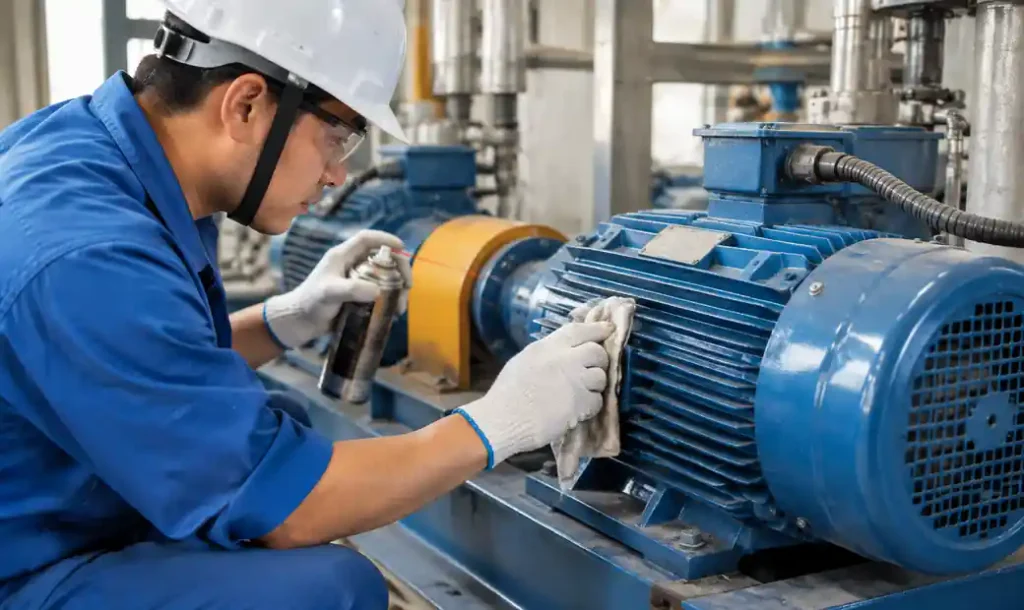
Weekly procedures (20-30 minutes): Torque motor mounting bolts to specification using proper torque wrench. Under-tightening allows movement and bolt fatigue; over-tightening damages threads. Remove motor covers and inspect eccentric weight bolts. Apply medium-strength threadlocker to any loosened bolts. Clean accumulated concrete dust from motor exteriors and ventilation openings using compressed air.
Monthly maintenance (45-60 minutes): Test motor bearing condition by rotating shafts manually—smooth rotation indicates healthy bearings, while grinding or clicking means replacement within 2-4 weeks. Measure motor current draw on all phases; readings should match within 5%. Inspect flexible couplings for cracks, missing chunks, or oil contamination that degrades rubber. Check vibration isolator condition—compression exceeding 25% of original height requires replacement.
Quarterly service (2-3 hours): Perform insulation resistance testing on motor windings using megohmmeter. Readings below 10 MΩ indicate moisture ingress or insulation degradation. Disassemble and inspect eccentric weight assemblies. Clean accumulated cement dust, verify weight bolt torque, and examine weight surfaces for cracks or deformation. Verify synchronization timing if your block machine uses electronic controls.
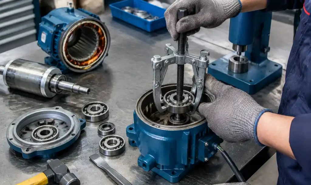
Bearing Replacement: Critical Procedure
Motor bearing failure is the leading cause of vibration system downtime. Proper replacement technique determines whether new bearings last 5,000 hours or fail within months.
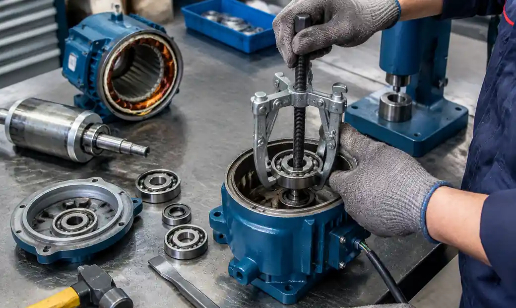
Remove motor from machine and clean thoroughly. Mark motor housing and end bell alignment before disassembly—misaligned reassembly causes vibration. Press bearings out using proper bearing puller; never hammer on bearing races. Heating housings to 80-100°C eases bearing installation, but never exceed 120°C or you’ll damage seals and lubricant.
Install bearings using proper driver that contacts outer race only for housing press-fits, inner race only for shaft press-fits. Pack bearings with lithium-based EP2 grease to 50-60% capacity—excessive grease causes overheating. Verify shaft runout below 0.03mm before reassembly; bent shafts destroy bearings within weeks.
After installation, run motor unloaded for 15-20 minutes, then check temperature. Properly installed bearings stabilize at 45-60°C. Temperatures exceeding 70°C indicate installation problems, inadequate lubrication, or contaminated bearings requiring immediate correction.
Troubleshooting Electrical Issues
Electrical problems cause 25-30% of vibration system failures but receive inadequate attention because mechanical issues seem more obvious.
Phase loss or imbalance: Most three-phase motors tolerate 2% voltage imbalance, but 5% imbalance increases temperature 25% and reduces life 50%. Measure voltage on all three phases during operation—readings should match within 5V. Phase loss causes immediate overheating and potential winding damage.
Loose connections: Vibration progressively loosens electrical terminals. Poor connections create resistance, heat, and voltage drops. Inspect terminal boxes monthly, tightening all connections to specification. Look for discolored terminals indicating overheating.
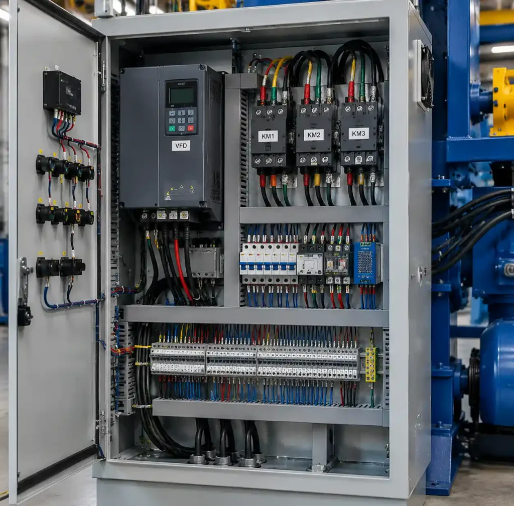
Contactor failures: Magnetic contactors energize motors and fail from dust contamination, pitting from arcing, or coil burnout. Contactors clicking rapidly indicate control voltage problems or mechanical binding. Replace contactors showing pitted contacts—they’ll fail during heavy production periods.
VFD-related problems: Variable frequency drives enable soft starts and speed control but introduce harmonic distortion. Ensure proper grounding and use shielded cables. VFDs require 40-45°C maximum ambient temperature; install cooling fans if enclosure exceeds this. Check DC bus capacitors annually—bulging tops indicate imminent failure.
Environmental Adaptations
Coastal and high-humidity environments: Salt air and moisture destroy motor windings progressively. Specify motors with IP65 or higher protection. Apply conformal coating to electrical connections. Perform insulation resistance testing quarterly instead of annually. Clean motors weekly to prevent salt accumulation.
Dusty production conditions: Concrete dust penetrates motor housings through ventilation openings and shaft seals. Install dust barriers around motors where possible. Use IP65 rated motors with sealed bearings. Clean motor exteriors weekly. Replace standard bearings with sealed units during routine replacement.
Temperature extremes: Operating below 0°C requires synthetic lubricants in bearings. Standard petroleum-based greases solidify, increasing starting torque 300-500%. Above 45°C ambient, derate motors 10-15% or install forced cooling. Monitor bearing temperatures closely in hot climates.
Integration with Supporting Equipment
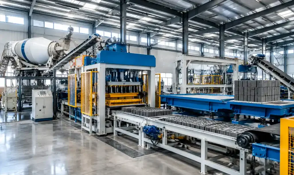
Vibration system performance depends on proper interaction with other machine components. Inspect concrete mixers for consistent batch quality—variations in moisture or gradation stress vibration systems. Verify hydraulic pressure stability; fluctuating pressure causes irregular pressing force that vibration cannot compensate for.
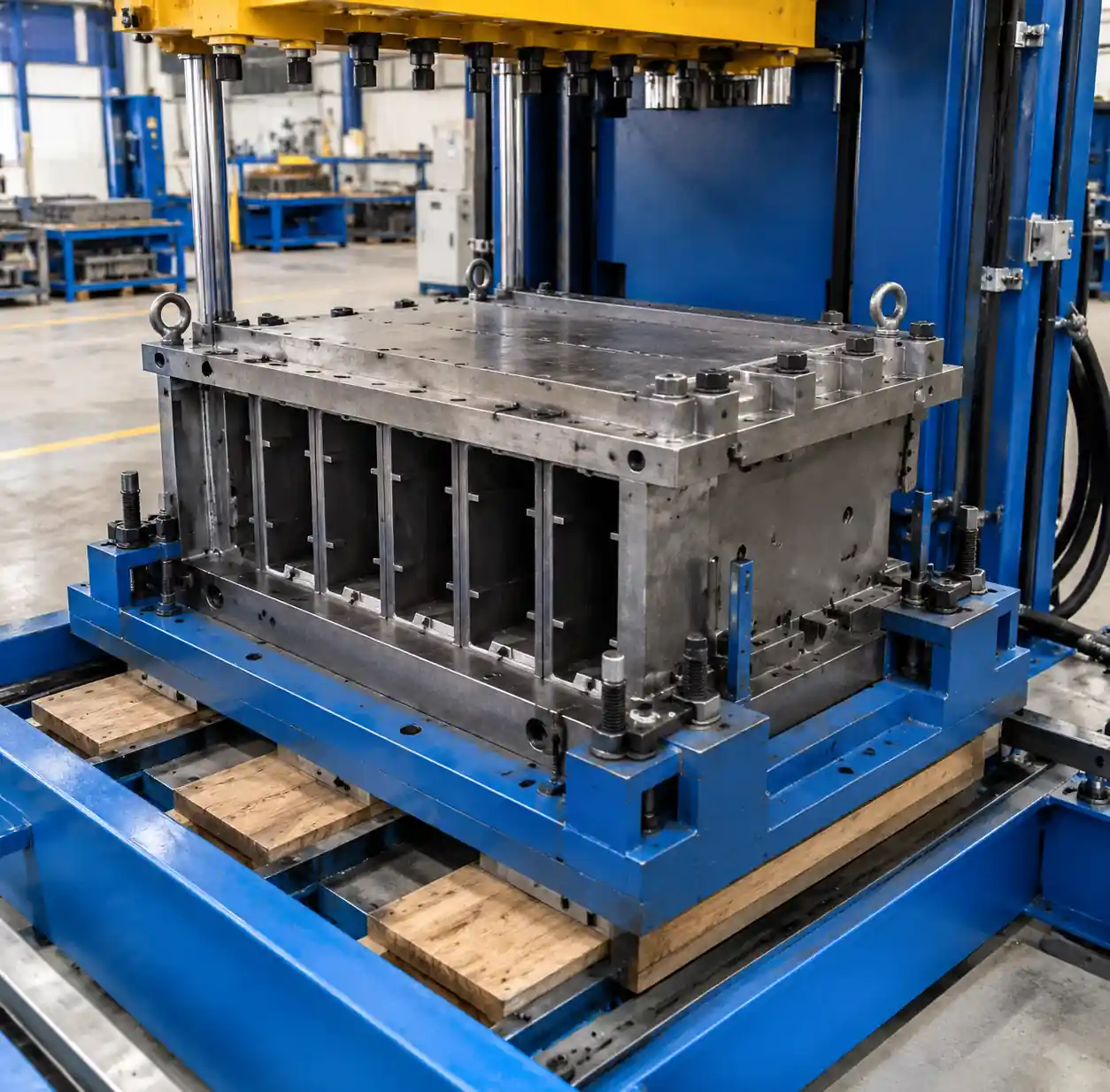
Monitor mold condition carefully. Worn or damaged molds increase vibration requirements 20-35% as concrete sticks and demolding becomes difficult. Clean molds thoroughly between shifts. Replace worn mold sections promptly—they reduce block quality and overload vibration systems.
Coordinate maintenance schedules between vibration systems and other components. Replacing vibration bearings while ignoring worn mixer paddles or clogged hydraulic filters wastes the opportunity for comprehensive improvement.
الأسئلة الشائعة
How long do vibration motors typically last?
Under proper maintenance, vibration motors achieve 15,000-25,000 operating hours. Bearings require replacement at 4,000-6,000 hours. Motors in harsh environments (dusty, humid, temperature extremes) need bearing replacement at 3,000-4,500 hours. Complete motor replacement becomes economical when bearing costs exceed 60% of new motor price.
Can I adjust vibration settings myself or do I need factory technicians?
Basic amplitude adjustment is straightforward—loosen locking bolts, rotate adjustment mechanism, retighten, and test. Most operators handle this after brief training. Frequency changes requiring VFD programming or motor rewiring need qualified technicians. Synchronization adjustment on dual-motor systems is critical—improper settings damage equipment.
What causes vibration motors to fail prematurely?
Bearing failures account for 65-70% of premature motor problems, caused by inadequate lubrication, dust contamination, or water ingress. Loose mounting bolts create secondary vibration that destroys bearings within weeks. Electrical issues (phase imbalance, voltage fluctuations) cause 20-25% of failures. The remaining 5-10% results from impact damage, overloading, or manufacturing defects.
Should I repair or replace failed vibration motors?
Motors under 7.5 kW usually cost less to replace than repair. Above 11 kW, repair becomes economical if only bearings need replacement. Never repair motors with burnt windings—rewinding rarely matches original performance. Replace motors that have failed twice; underlying design or application issues make third failures likely.
How do I know if vibration settings are optimal?
Demolded blocks tell the story. Optimal vibration produces uniform surface texture, releases cleanly from molds, and achieves consistent compression strength within 3-5% variation. Blocks sticking to molds indicate insufficient vibration. Surface segregation (coarse aggregates visible on faces) means excessive vibration. Conduct crush tests weekly—declining strength reveals vibration problems before visible symptoms appear.
What spare parts should I stock for vibration systems?
Maintain complete bearing sets for all motors (most critical), flexible coupling replacements, eccentric weight bolt sets with threadlocker, motor contactors and overload relays, and vibration isolator sets. For automatic systems producing 10,000+ blocks daily, stock complete backup motors for critical positions. Two-day shipping delays cost more than spare part inventory.
الخلاصة
Vibration system reliability determines block machine profitability. Manufacturers implementing structured maintenance—daily sound checks, weekly bolt torque verification, monthly bearing assessment, and quarterly electrical testing—prevent 70-80% of unplanned failures while extending motor life 40-60%.
The diagnostic procedures and troubleshooting guides in this article address the actual problems block manufacturers encounter daily: bearing wear, synchronization loss, amplitude misadjustment, and electrical deterioration. Focus maintenance resources on bearing condition monitoring and mounting bolt torque verification—these two tasks alone eliminate most common failures.
Start with baseline measurements tomorrow: record motor temperatures, current draw, and vibration characteristics during normal production. These numbers reveal developing problems weeks before visible failures occur. Contact Raytone Block Machinery for technical support, genuine replacement motors, and customized vibration system optimization.